This is the summary of the people in the industry when summarizing the fixture design, but it is far from simple. In the process of contacting various schemes, we found that there are always some positioning and clamping problems in the preliminary design. In this way, any innovative scheme will lose its practical significance. Only by understanding the basic knowledge of positioning and clamping can we fundamentally ensure the integrity of the fixture design and processing scheme.
Locator knowledge
1、 Basic principle of positioning from the side of the workpiece
When positioning from the side of the work-piece, the three-point principle is the most basic principle, as is the support. This is the same as the principle of the support, which is called the three-point principle, derived from the principle of “three points not on the same line determine a plane”. Three of the four points can determine a face, so a total of four faces can be determined. However, no matter how to locate, it is quite difficult to make the fourth point in the same plane.
▲ Three point principle
For example, when using 4 fixed height positioners, only 3 points in one place can contact the workpiece, and the remaining 4 points are still very likely not to contact the workpiece.
Therefore, when configuring the positioner, it is generally based on three points, and the distance between these three points should be increased as much as possible.
In addition, when configuring the positioner, it is necessary to confirm the direction of the applied processing load in advance. The direction of the processing load is also the direction of the tool handle/tool travel. The positioner is configured at the end of the feed direction, which can directly affect the overall accuracy of the workpiece.
Generally, the bolt type adjustable positioner is used for positioning the blank surface of the workpiece, and the fixed type (the CNC Turning Parts contact surface is ground) positioner is used for positioning the machining surface of the workpiece.
2、 Basic principle of positioning from workpiece hole
When using the hole processed in the previous process of the workpiece for positioning, it is necessary to use a tolerance pin for positioning. By matching the accuracy of the workpiece hole with the accuracy of the pin profile and combining according to the fit tolerance, the positioning accuracy can meet the actual requirements.
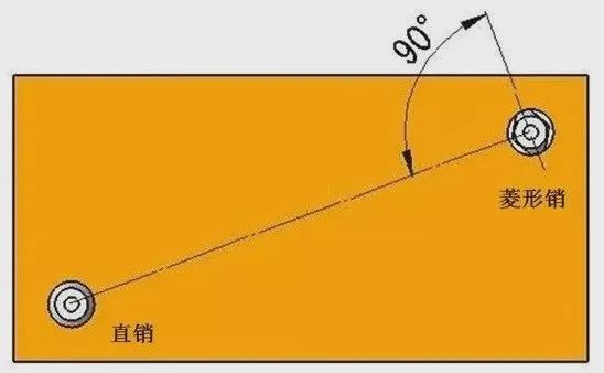
In addition, when using the pin for positioning, generally one uses a straight pin and the other uses a diamond pin, so it will be more convenient to assemble and disassemble the workpiece. It is rare for the workpiece to get stuck with the pin.
▲ Positioning with pin
Of course, it is also possible to use straight pin for both pins by adjusting the fit tolerance. For more accurate positioning, it is usually most effective to use a straight pin and a diamond pin.
When a straight pin and a diamond pin are used, the connecting line in the configuration direction (where the diamond pin contacts the workpiece) of the diamond pin is usually 90 ° perpendicular to the connecting line between the straight pin and the diamond pin. This configuration is for angular positioning (the rotation direction of the workpiece).
Relevant knowledge of clamp
1、 Classification of grippers
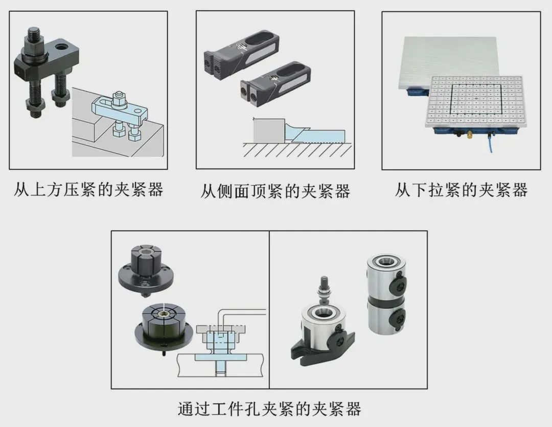
According to the clamping direction, it is generally divided into the following categories:
Next, let’s look at the characteristics of various clamps.
1. Clamps pressed from above
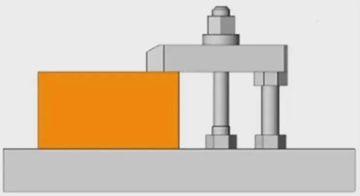
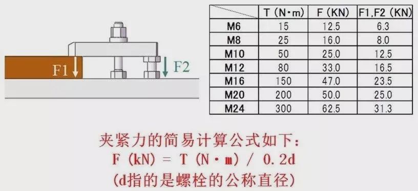
The clamping device that is pressed from above the workpiece has the least deformation during clamping, and is the most stable during workpiece processing. Therefore, in general, the first consideration is to clamp from above the workpiece. The most common fixture for pressing from above the workpiece is a manual mechanical fixture. For example, the following figure is called “loose leaf type” clamp. The clamp combined by pressing plate, stud bolt, jack and nut is called “loose leaf” clamp.
Moreover, press plates with different shapes can be selected according to the shape of the workpiece. Such as CNC Machining Parts, Turning Parts and Milling Parts.
The relationship between the torque and clamping force of the loose leaf type clamp can be calculated by the pushing force of the bolt.
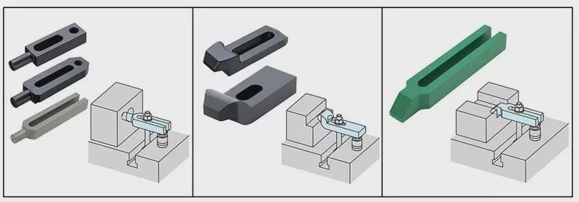
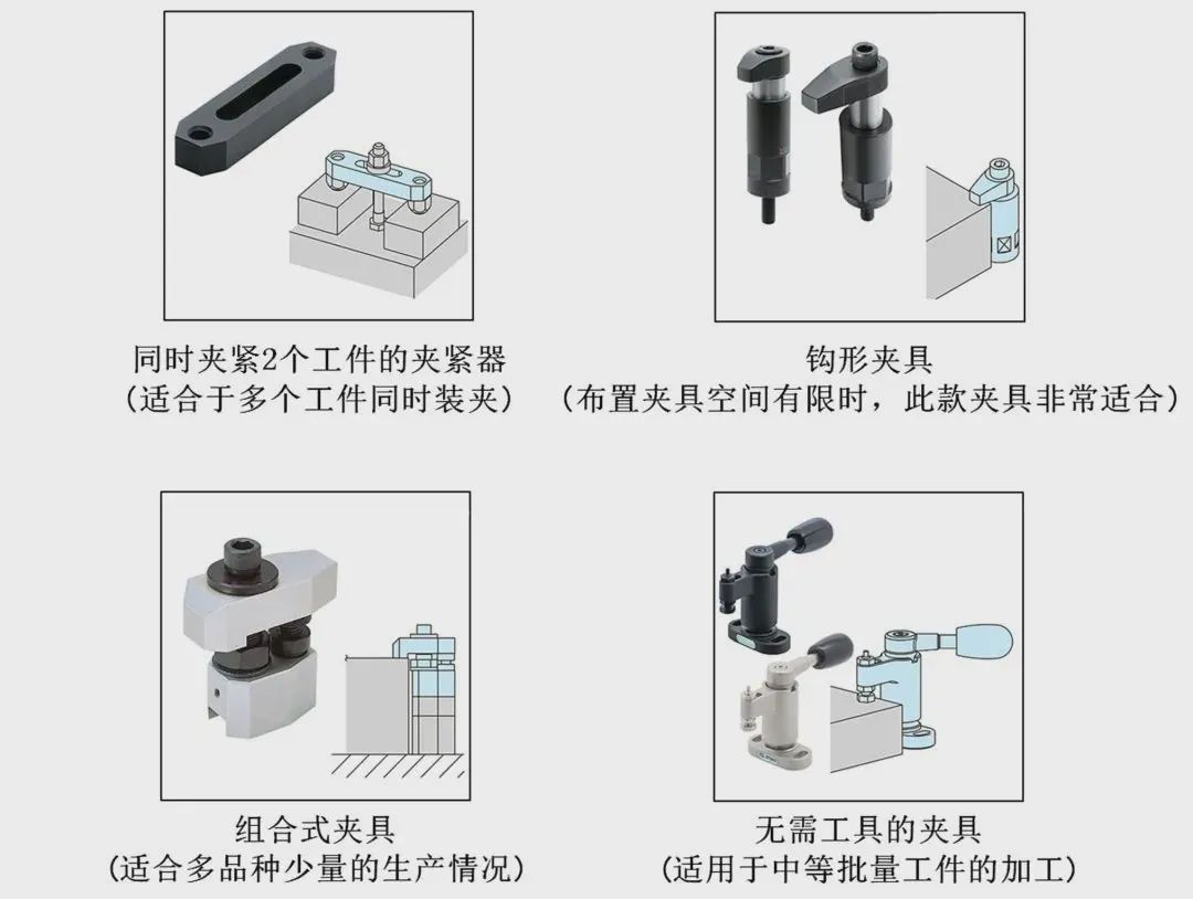
In addition to the loose leaf clamp, the following similar clamps are available for clamping from above the workpiece.
2. Clamping clamp from the side
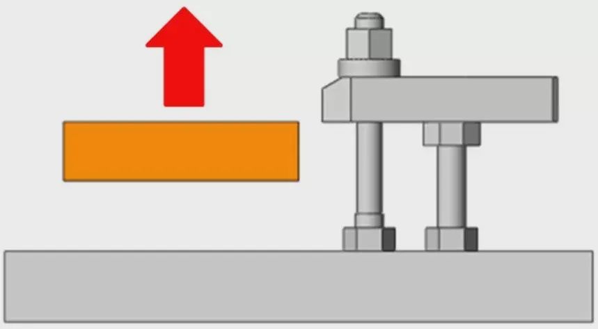
Originally, the clamping method of clamping the work-piece from above is the most stable in accuracy and the minimum in processing load of the work-piece. However, when it is necessary to process above the workpiece, or it is not suitable to clamp from above the workpiece, which makes it impossible to clamp from above the workpiece, you can choose to clamp from the side of the workpiece. However, relatively speaking, when the workpiece is clamped from the side, it will produce a floating force. How to eliminate this force must be paid attention to when designing the fixture.
As shown in the figure above, the side clamp also has an oblique downward force while producing thrust, which can effectively prevent the workpiece from floating up.
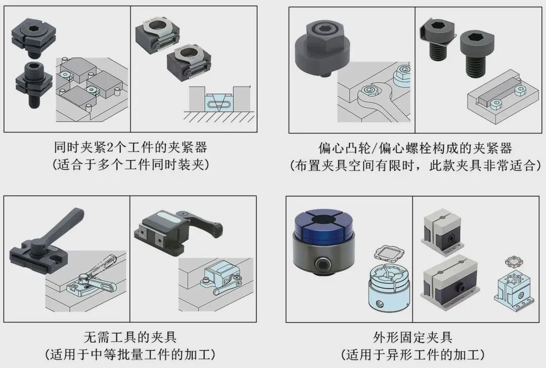
Clamps that clamp from the side also have the following similar clamps.
3. Clamping device for tightening workpiece from pull-down
When machining the upper surface of a thin plate workpiece, it is not only impossible to clamp it from the top, but also unreasonable to compress it from the side. The only reasonable clamping method is to tighten the workpiece from the bottom. When the workpiece is tensioned from below, if it is made of iron, a magnet type clamp can usually be used. For non-ferrous metal workpieces, vacuum suction cups can generally be used for tensioning.
In the above two cases, the clamping force is proportional to the contact area between the workpiece and the magnet or vacuum chuck. If the processing load is too large when processing small workpieces, the processing effect will not be ideal.
In addition, when using magnets or vacuum suckers, the contact surfaces with magnets and vacuum suckers need to be made to a certain degree of smoothness before they can be used safely and normally.
4. Clamping device with holes
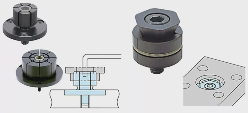
When using a 5-axis machining machine to process multiple faces at the same time or mold processing, in order to prevent the impact of fixtures and tools on the processing, it is generally appropriate to use the hole clamping method. Compared with the way of clamping from the top and the side of the workpiece, the way of hole clamping has less load on the workpiece and can effectively deform the workpiece.
▲ Direct processing with holes
▲ Set rivet for clamping
2、 Pre clamping
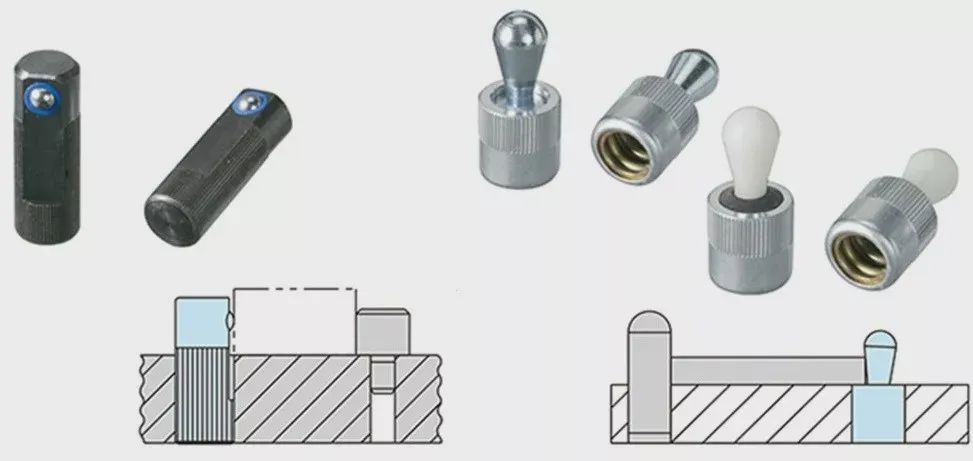
The above are mainly about the clamping fixture of the workpiece. How to improve the operability and use pre clamping is also crucial. When the workpiece is vertically set on the base, the workpiece will fall due to gravity. At this time, the gripper must be operated while holding the workpiece by hand.
▲ Pre clamping
If the workpieces are heavy or most of them are clamped at the same time, the operability will be greatly reduced and the clamping time will be very long. At this time, the use of this spring type pre clamping product can enable the workpiece to operate the gripper in a stationary state, greatly improving the operability and reducing the clamping time of the workpiece.
3、 Precautions when selecting the gripper
When multiple types of clamps are used in the same tooling, the tools for clamping&loosening must be unified. For example, as shown in the left figure, when using a variety of tool wrenches for clamping operation, the overall burden of the operator will become larger, and the overall clamping time of the workpiece will also become longer. For example, in the figure on the right below, tool wrenches and bolt sizes are unified to facilitate field operators.
▲ Workpiece clamping operability
In addition, when configuring the gripper, it is necessary to consider the operability of workpiece clamping as much as possible. If the workpiece needs to be tilted during clamping, the operability is very inconvenient. This situation needs to be avoided when designing the fixture.
Post time: Oct-24-2022


